Introduction
I have had an RK3128 TV box sitting around for a long time. I got Armbian booting on it years ago, but the setup was quite complicated, with a lot of manual steps and one-off fixes. Even though I use it day to day as a small Linux box, I never shared it with anyone else because reproducing it would require too much manual work, and I was too busy to write a proper guide.
After I posted the note about running Debian on the S805 box, someone asked about the RK3128 one. He was reusing old TV boxes for a small project to reduce electronic waste, which was reason enough to revisit it.
This article is not an installation guide. It is a technical note on cleaning up that old setup and figuring out which parts were actually necessary to make it reproducible.
RK312x Booting note
Booting process
At a high level, the boot flow is simple: power on, run Miniloader, load U-Boot, load the kernel, then boot the operating system. The real details are messier, but this is the part that matters for the rest of this note.
|
|
When the board powers on, the SoC first executes its internal boot ROM. It then looks for a Miniloader on the configured storage. If it finds one, it loads it into the small internal SRAM and starts it. Miniloader is Rockchip’s closed-source first-stage bootloader. It is usually specific to a CPU family and, in practice, often tied to the board’s DRAM initialization and storage setup as well. Its main job is to bring up enough hardware, especially DRAM, so the next stage can run normally.
Once that is done, Miniloader loads U-Boot. U-Boot then takes over the more flexible part of the process: reading the kernel, device tree, and optional initramfs from storage, setting the kernel command line, and jumping into the kernel.
From there, the Linux kernel initializes the rest of the hardware, mounts the root filesystem, starts init, and brings the operating system up.
Boot mode
Besides the normal boot path, Rockchip also has a USB recovery path based on the Rockusb protocol. On these old boards, the two states you usually see in RKDevTool are MaskROM and Loader, but they are not the same thing.
MaskROM mode is the lowest-level recovery mode. In this state, the SoC is still running only the BootRom code stored inside the chip itself. Rockchip’s official docs also call this Bootrom mode or Maskrom mode. The board enters this state when BootRom cannot find valid boot firmware on the storage, or when we force that failure on purpose by shorting the boot storage lines.
The important limit of MaskROM mode is that DRAM is not available yet. Because of that, only a very small USB download path is available. Rockchip’s own tools handle this with the db command: they send a special loader over USB, initialize DRAM, and switch the board into a more capable Rockusb state.
Loader mode is that next step up. In practical RKDevTool terms, it means the board is no longer using the raw BootRom USB path. A Rockusb firmware such as usbplug or the vendor miniloader is already running, DRAM is already initialized, and normal flashing commands become available. On these old vendor-based RK3128 boards, this is the mode you usually want for normal writing and recovery work.
So the distinction is:
MaskROM: BootRom only, no DRAM, limited USB download pathLoader: a downloaded or booted Rockusb loader is already running, DRAM is available, and flashing is easier
|
|
Storage types
NAND vs eMMC
This class of TV box is old enough that it may come with two storage types: eMMC or NAND. In short:
- NAND is a raw storage device. Wear management and other low-level handling must be done in software.
- eMMC is NAND plus a controller. Wear leveling and device commands are handled by the controller.
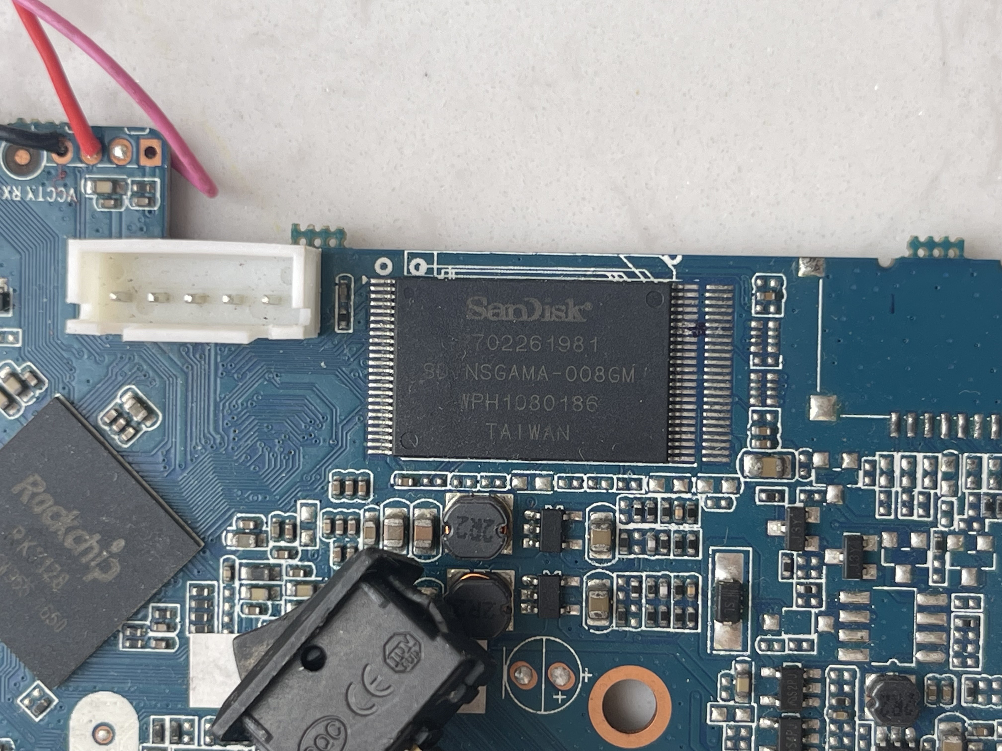
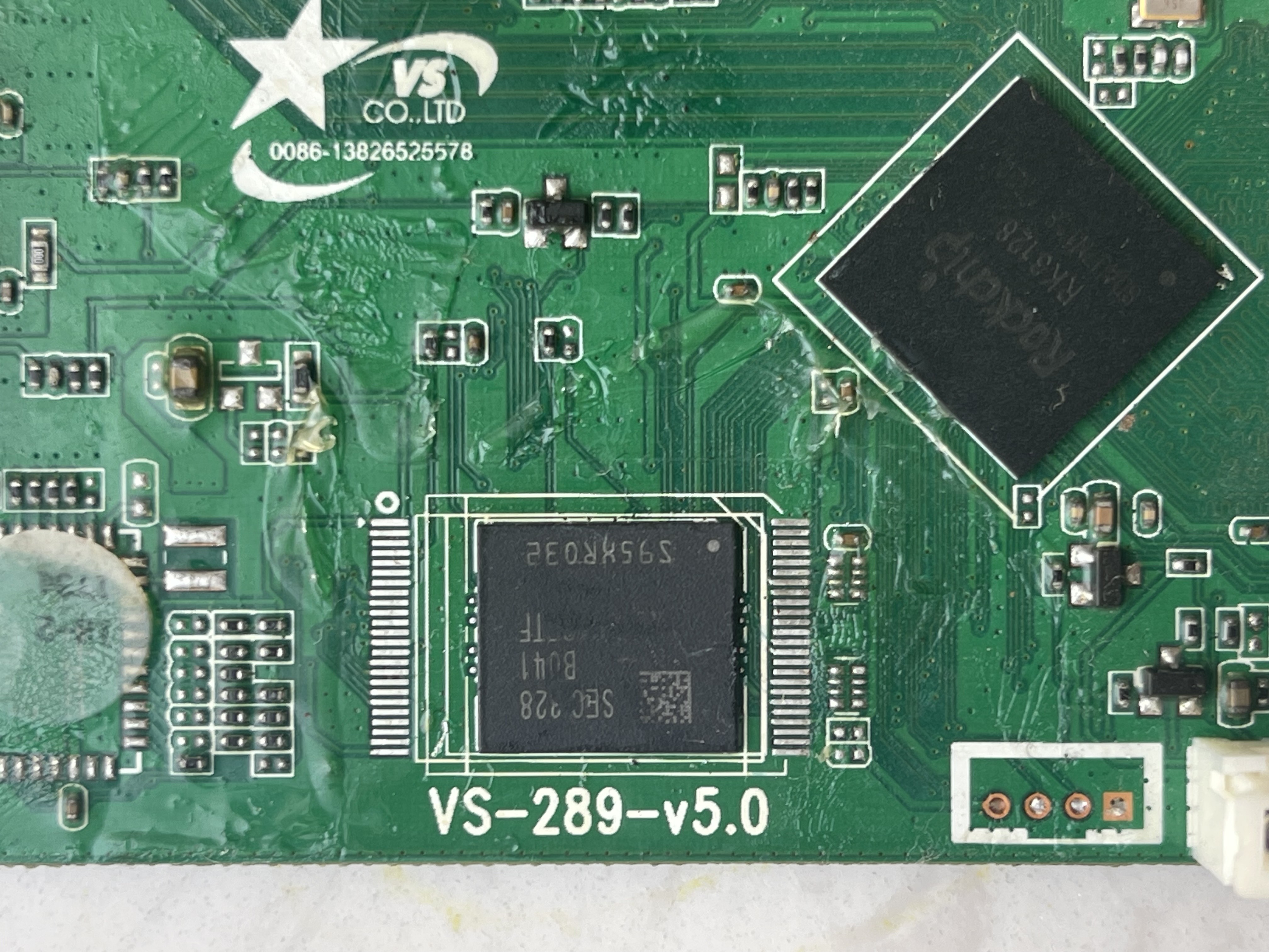
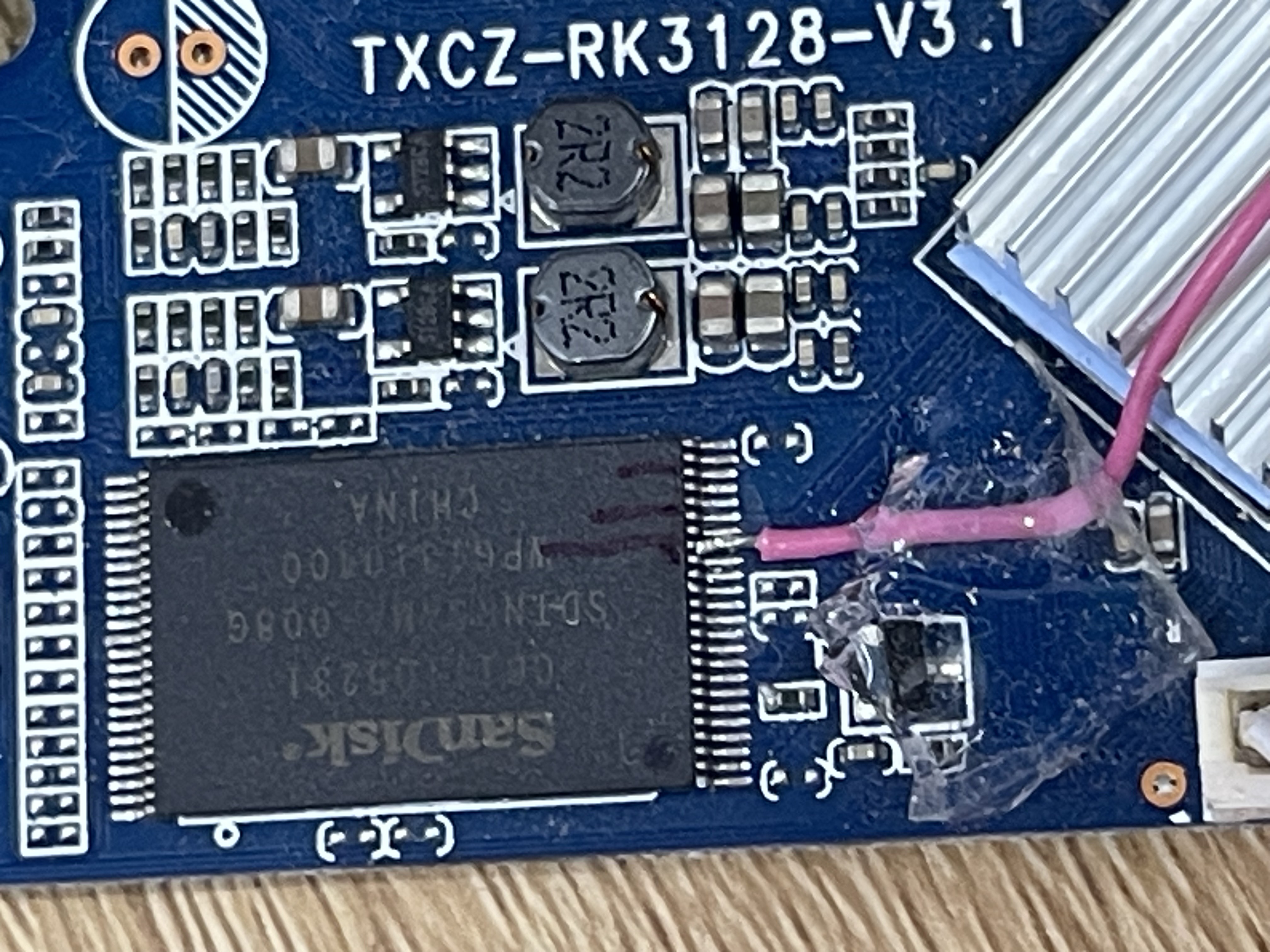
Here are photos of my two boards with different storage types. This is not a perfect rule, but in practice the chip with visible pins is usually NAND, while the package without visible pins is usually eMMC. Identifying the storage type matters because I may need to adjust the Armbian boot setup in the next steps.
Booting into MaskROM mode
- Normally, you just need to boot into
Loadermode to update or install a new ROM. On this board, the easiest way to do that is to keep holding the reset button while powering it on. But sometimes you break things badly enough that you needMaskROMmode to recover it. - For NAND devices, you can short either
ALEorCLE(pin 16 or pin 17) toGNDwhile powering on the board. The board will then fail to recognize the NAND and enterMaskROMmode. You may also find advice telling you to shortD0or other data pins toGND. NEVER DO THAT. EVER. It may appear to work a few times, but it can damage the CPU’s NAND interface and leave the board unable to detect NAND again. You can also short pin 16 and pin 17 together. - If counting the pins directly is inconvenient, first find the side that has pin 1, then count backward from pin 24 on that side. The two pins I use are the 8th and 9th pins from pin 24. In the photo below, I soldered a wire to pin 16. Whenever I need to enter
MaskROMmode, I just short that wire to the USB port.
- For eMMC devices, this type of board often still has the NAND pads routed out, so you can use the same pins described above to get the same effect.
Rockchip Partitioning
Rockchip partitioning
Like many other vendors, Rockchip uses its own proprietary partition table together with its NAND driver. In this partitioning system, everything is counted in 512-byte blocks.
The first 0x2000 blocks (4 MiB) form a small region used for Miniloader, partition layout, and system parameters. I call it the Loader partition. After that region, the rest of the storage is split into partitions such as uboot, trust, system, and so on.
Partitioning Rockchip storage is actually very simple. We upload a file called parameter.txt to address 0x0 of the storage, and then Miniloader uses it to partition the device. After it is written, this parameter data is stored at both the beginning and the end of the Loader partition. The layout of the Loader partition is below:
|
|
Below is a sample of the parameter I took from a ROM running Android 7.1.2.
|
|
The partition information is written inside CMDLINE. Miniloader reads it and updates the partition table from it. Later, the rknand driver reads that partition table and creates logical devices named rknand_<partition_name>. For example, for the boot partition you will see a device named rknand_boot. Then we can mount /dev/rknand_boot as an ext4 filesystem.
RKDevTool
RKDevTool is a Windows tool provided by Rockchip. It can be used to write almost anything to NAND or eMMC. It gets updated quite frequently, but in my experience version 2.69 is the most stable. There is also a Linux version if you prefer that.
Some notes for this tool:
- Miniloader and
parameteruse the same address,0x0. That is intentional, becauseparameteris input for Miniloader, not a separate raw text blob written to storage by itself. - In
MaskROMmode, all buttons exceptRunare not working. After Miniloader is downloaded, the other buttons start working. At that point, even if the tool still says the board is inMaskROMmode, it is effectively inLoadermode.
Building U-boot
One thing I like about Rockchip is that they publish a fairly complete vendor U-Boot tree together with the extra binaries needed for the older boot flow. Their basic U-Boot documentation is here: https://opensource.rock-chips.com/wiki_U-Boot.
For RK3128, those vendor changes still matter, especially around the old storage and loader flow. I also made a few tweaks in my own fork to make it work better on these TV boxes: https://github.com/chieunhatnang-personal/u-boot-rk3128-tvbox. The main changes are:
- Enable booting from all available devices in the order
USB -> SD card -> eMMC -> NAND -> PXE. If no valid boot script (boot.scr) or bootable ext filesystem is found, U-Boot falls back to the next device. This was the hardest part, because the vendor source tree does not contain correct drivers and settings for all of those storage paths. In practice, I often had to make the device work in Linux first, then use the kernel logs as a reference while fixing U-Boot. - Add a few utility commands
- Add 9 seconds wait for Ctrl+C to stop autoboot and give U-boot command
- Add support for the reset key. When pressing it, it will goes to the MaskROM mode, similar to the stock U-boot.
To build it, we need a 32-bit ARM cross toolchain and the rkbin directory, because Rockchip’s build scripts still depend on binaries and helper tools from there. Rockchip’s own vendor documentation uses gcc-arm-8.3-2019.03-x86_64-arm-linux-gnueabihf for 32-bit ARM boards. In my case, I built it with gcc-linaro-6.3.1-2017.05-x86_64_arm-linux-gnueabihf, which worked fine for this tree. The official rkbin repository is here: https://github.com/rockchip-linux/rkbin
After getting those, we need to adjust the paths in make.sh. Then we can simply run:
|
|
After the build finishes, the useful output files at the project root are:
|
|
The most important one for recovery work is rk3128_loader_v2.12.263.bin. This is the loader image that RKDevTool can download while the board is in MaskROM mode. Once that succeeds, the board effectively moves into Loader mode, and then the rest of the images can be written normally.
Building IDBLoader.img
idbloader.img and rkxx_loader_vx.xx.xxx.bin are easy to confuse, but they are not the same thing.
idbloader.img is the image written to the boot media itself, for example SD card or eMMC. Rockchip BootRom reads it from sector 0x40 during normal boot. It contains:
- the Rockchip IDBlock header, so BootRom can recognize the image
- the DDR initialization binary, which runs first in internal SRAM
- the miniloader, which runs after DRAM is available and loads the next stage
So idbloader.img is a real boot image for the storage device.
rkxx_loader_vx.xx.xxx.bin is different. That file is Rockchip’s USB upgrade loader used by tools like RKDevTool and rkdeveloptool when the board is in MaskROM mode. According to Rockchip’s own boot docs, this file is a package made from:
ddr.binusbplug.binminiloader.bin
Its job is recovery and flashing over USB, not normal boot from storage. In particular:
db rkxx_loader_vx.xx.xxx.bindownloads the USB loader, runsusbplug, and initializes DRAM- after that, the board behaves like a Rockusb device in a DRAM-enabled loader state
ul rkxx_loader_vx.xx.xxx.binis effectivelydbplus writing the loader to the normal boot area on eMMC
So this file is for the USB upgrade path. It is not the file you write directly to SD card or eMMC as the normal bootloader image.
For this RK3128 work, I did not build the DDR init binary or the miniloader myself. I found the two required files directly in the rkbin folder:
rk3128_ddr_300MHz_v2.12.binrk312x_miniloader_v2.63.bin
Then I used them directly to create idbloader.img:
|
|
The first command creates the Rockchip idbloader.img header and packs the DDR init binary into it. The second command appends the miniloader. The result is a complete idbloader.img that BootRom can load from the boot media.
Building Linux kernel 4.4.194
This was the hardest part by far. Rockchip does publish kernel source at https://github.com/rockchip-linux/kernel, but the tree has many branches and very little guidance on which one actually fits an old TV box board. I spent quite a bit of time reading through the Armbian RK322x work, especially jock’s thread here: https://forum.armbian.com/topic/34923-csc-armbian-for-rk322x-tv-box-boards. Even with that as a reference, this part was still messy.
The first attempt
Out of all the branches in Rockchip’s kernel tree, I started with the one based on Linux 4.4.194. The main reason was practical: I wanted something close enough to the older RK322x Armbian userspace that I could reuse jock’s root filesystem with as few surprises as possible. I even changed the kernel sub-version to match with his build (4.4.194-rk322x) to reuse his drivers.
Inside that tree, the two obvious starting points were rk3128_linux.config and rk3128_linux_spi_nand.config. Both built without much trouble, and I could get some basic parts of the system working, such as CPU bring-up and USB. But a lot of the board-specific hardware was still broken. I also tried most of the DTS files with the rk3128 or rk3128h prefix under the vendor DTS directory, and the result was still a mess. At that point it became clear that “building the kernel” mostly meant iterating on DTS and driver fixes, not just running make.
CPU stepping
CPU frequency scaling was another part that looked simple at first and then turned into a small detour. The board would boot, but the CPU stayed at 600 MHz. That was enough to keep the system usable, so it did not immediately look broken in the same obvious way as storage or Wi-Fi, but it was clearly not the intended behavior.
My first assumption was the usual one: maybe the DTS was missing the correct CPU OPP table, or maybe the regulator wiring was incomplete. The vendor RK3128 Android DTS did have a more complete CPU voltage table, and the RK322x tree I was reusing also had working DVFS on very similar Cortex-A7 TV boxes. So I started by merging those ideas into rk3128-linux.dts.
That still did not actually enable scaling. The useful clue was not the current frequency itself, but the absence of the usual cpufreq sysfs nodes. There was no policy0, no scaling_max_freq, and no scaling_available_frequencies. That meant the problem was deeper than “the governor picked a low speed”. The cpufreq policy had never been created at all.
Normally, this kind of CPU stepping needs a programmable regulator. On this class of cheap hardware, I first assumed the CPU rail would just be fixed and that real DVFS was therefore not possible. But Rockchip took a cheaper path here: the SoC already has PWM outputs, and the board uses those PWM lines to control the CPU and logic rails. So from the kernel side, the important part was not finding a fancy PMIC. It was describing the rail as a pwm-regulator correctly. That is also why the RK322x reference DTS ended up being a better clue than the leftover rk816 node in the original board DTS. Once I switched the CPU rail to a PWM regulator on pwm1, added the logic rail on pwm2, and pointed cpu-supply, mali-supply, and center-supply to those rails, cpufreq finally came up correctly.
There was one more small mismatch after that. The OPP table I had copied still used a 1.425 V maximum, while the PWM regulator definition on this board only allowed a lower ceiling. Because of that, the kernel rejected every CPU OPP as unsupported by the regulator. After aligning the regulator limits and the OPP table, the cpufreq policy appeared as expected.
At that point the board finally exposed the proper frequency table. The simplest way to check it was:
|
|
For quick testing, these were the sysfs knobs I ended up using most often:
|
|
One small trap here was that the governor did not stay where I set it. Even though the kernel tree itself was built with interactive as the default governor, after reboot the board still came back as ondemand. That turned out not to be a kernel problem at all. It was a userspace leftover from the RK3229 root filesystem:
|
|
That file is applied during boot and writes directly to the same cpufreq sysfs nodes, so in practice it overrides the boot-time governor and min/max limits. On RK3128, that MAX_SPEED=1500000 setting was clearly just old RK3229 baggage, because the actual RK3128 frequency table stopped at 1200000. The safer version for this board was:
|
|
The important correction is that the governor was not the real bug either. I originally suspected that because Firefox and video playback would trigger random hard lockups, and one of the traces happened to involve the ondemand workqueue. That turned out to be misleading.
What actually failed was the voltage table I first copied from RK3229. RK3229 and RK3128 are close relatives, but not identical. The RK3229 datasheet allows a lower CPU voltage range: roughly 0.9 V minimum and 1.0 V typical. RK3128 is specified higher: roughly 1.0 V minimum and 1.1 V typical. In other words, the low-voltage DVFS values that are reasonable on RK3229 are already too aggressive for RK3128.
That mistake showed up very clearly in the early OPP table I used. I had copied low points like:
216 MHzat950 mV408 MHzat950 mV600 MHzat975 mV
Those values are in the RK3229 comfort zone, but they are below where RK3128 should have much margin. The old vendor Rockchip code also adds another complication on top of that: it can pick different voltage variants (L0, L1, L2) from efuse leakage data. So even when the visible OPP table looked acceptable, the actual voltage used on a particular chip could end up a bit lower again.
That is why the board behaved in such a confusing way. A fixed 1200 MHz stress test could run for hours without problems, so the top speed itself was clearly not the issue. The crashes happened instead during dynamic transitions, especially when the system was lightly loaded and the governor tried to walk the CPU back down into those low-voltage states. Firefox was a very good trigger because it causes a lot of bursty load changes: wake up, render, idle, wake up again, start a video, and so on. The system was not failing because it needed more peak frequency. It was failing because some of the low-frequency, low-voltage states were not stable on RK3128.
So the real fix was not “use a different governor” and not “work around some kernel bug”. The real fix was to stop treating RK3128 like RK3229 in the DVFS table:
- keep the PWM regulator wiring, because that part was correct
- disable the leakage-based voltage selection for the CPU OPP table
- use fixed voltages instead of per-chip lower-voltage variants
- raise the CPU regulator floor above the RK3128 minimum
- put back the low frequencies only with RK3128-safe voltages
The stable table I ended up with was:
216 MHzat1.05 V408 MHzat1.05 V600 MHzat1.10 V816 MHzat1.20 V1008 MHzat1.20 V1200 MHzat1.35 V
So the practical lesson here is a bit different from what I first wrote:
cpufrequtilsmay still override your chosen governor at boot, so it is worth checkingperformanceorinteractivecan make the system look more stable because they reduce how often it enters the low OPPs- but if the voltage table itself is wrong, changing the governor only changes how often you hit the problem
For this board, the root cause was the RK3229-style low-voltage OPP table, not the governor itself.
RAM dynamic frequency
RAM frequency scaling looked similar to CPU scaling at first, but it turned out to be much less predictable. The vendor DTS already has a dmc node and a DDR OPP table, and on some RK3128-family boards that dynamic path works fine. In fact, one of my boards is very stable with dynamic DDR scaling, while another is unreliable enough to hang. So this is not one of those cases where dynamic DDR scaling is universally broken. It seems to depend much more on the specific board, its DRAM chips, and the routing.
At first I also suspected the Miniloader, because Rockchip’s old boot flow does DRAM initialization very early. But in this case I was using the same Miniloader on both boards and still getting different results, so the Miniloader was probably not the main variable here. On the unstable board, dynamic DDR scaling was not reliable. With the DMC path enabled normally, the system could hang during boot or later under load. If I disabled DMC completely, the board became stable again, and the RAM stayed at the bootloader-set rate, which on this board looked like about 300 MHz. So the first useful step was not to chase the dynamic governor immediately, but to test fixed DDR targets one by one with overlays.
The first thing that confused me was that the number in the DTS is not necessarily the real frequency you get. The DDR driver asks for a target frequency, but the final rate can be rounded by Rockchip’s DDR clock handling path. In other words, the overlay name is really “request this DDR OPP”, not “guarantee this exact final clock”. On my board, selecting 330 MHz did not actually give 330 MHz. The reported live clock became 396 MHz, which means about 792 MT/s effective.
That rounding also means the results are not monotonic in the way you might expect. On this board:
- disabling DMC was stable and left the RAM around
300 MHz - selecting
330 MHzwas also stable, but the real clock became396 MHz - selecting
400 MHzdid not give a higher stable result; it fell back to300 MHz - selecting
600 MHzcaused a hard kernel hang
That is also why I switched to testing the real DDR steps already present in the RK3128 DMC table: 300, 330, 400, 600, 666, 700, 786, and 800. Even then, those numbers should still be treated as requested operating points, not a promise that the live clock will match them exactly on every board.
So the practical approach here is much more conservative than I first expected:
- if dynamic DDR scaling works on a board, great, leave it enabled
- if it does not, switch to a fixed static DDR overlay first
- start from the lowest stable point and move up one step at a time
- after each step, check the real live DDR clock instead of trusting the overlay name
- only keep going if the board survives both boot and real workloads
For this particular board, the useful lesson was that “higher configured DDR” does not necessarily mean “higher real DDR”, and it definitely does not mean “stable”. The safe path was to treat each DDR step as an experiment. In practice, 330 was the best fixed choice here, not because 330 MHz itself was special, but because it rounded to a stable 396 MHz on this board while the higher requests did not behave well.
GPU
For desktop testing, I installed LXDE, mainly because it is light enough that the board stays usable while I debug the rest of the system.
GPU support was another place where I had to correct my own expectations. RK3128 does have a Mali-400 MP, and on the vendor 4.4 kernel it can still be used through the old proprietary Utgard stack. Following jock’s old RK322x legacy media notes, I tried the same userspace direction here, especially libmali-rk-utgard-400-r7p0-x11_1.7-1_armhf.deb together with the armsoc Xorg driver. After also disabling the inherited RK322x Lima Xorg fragment from the reused root filesystem, es2_info finally reported:
|
|
So the GPU is not dead. The board really can run the old Mali userspace stack, but only in a narrow legacy sense. It is good enough for EGL / OpenGL ES 2.0 applications. It is not a modern Mesa/Lima desktop stack, and it does not provide a clean accelerated GLX path for normal Linux desktop software. In Xorg, the system still ended up falling back to DRISWRAST for GLX, so desktop OpenGL and modern browser rendering stayed mostly on software paths.
That also explains why browser testing was so disappointing. Firefox could sometimes feel a bit smoother to move around, but video playback inside the browser was still poor. More importantly, after bringing in the old libMali userspace stack, the kernel became unstable enough to crash randomly. After a lot of trying, I ended up going back to the plain Mesa software path, which on this board means llvmpipe.
That fallback is less exciting, but much more useful in practice. Performance was not dramatically worse for the lightweight desktop workloads I actually care about, while stability was clearly better. With llvmpipe, the system no longer suffered the random crashes I was seeing with the old Mali userspace stack.
Video playback has a similar limitation. The GPU does not decode video; that job belongs to the old Rockchip video blocks and the legacy RKMPP userspace on the 4.4 vendor kernel. That may still help local media players, but browser video sites, especially YouTube, are still a bad workload for this board.
So the honest summary is:
- the legacy Mali stack works for some
OpenGL ES 2.0applications - but for a normal GUI desktop, I ended up back on Mesa
llvmpipe llvmpipewas about the same for my practical desktop use, but much more stable- so if someone just wants to install a GUI on this board, the software path is the safer choice
RKNAND
rknand was especially important here. RK3128 is older and cheaper than RK3229, and many of these boxes use raw NAND instead of eMMC. On RK3229 boxes, eMMC is much more common, so storage support tends to be less painful there. On RK3128, if rknand does not work, the whole bring-up becomes much less useful.
After trying a long list of DTS combinations, I accidentally tried an rk3126 DTS. That was the first time rknand suddenly started working. I would not generalize that into “RK3126 DTS is the correct DTS for RK3128”, but it was a useful clue: in this vendor tree, the DTS names were not always a reliable guide, and some RK3128 TV boxes were clearly closer to the RK3126 reference setup in the storage path than the obvious file names suggested.
eMMC
eMMC was trickier than rknand because the failures changed shape as the board got closer to working. At the start, the host initialized, but the card never completed bring-up and Linux ended with mmc1: error -110 whilst initialising MMC card. The Android reference DTS and some working RK322x overlays suggested several board variants, so I tested the obvious ones first: alternate emmc_cmd1, explicit emmc_pwr, 4-bit fallback, and a few different timing ideas. Those experiments were useful as diagnostics, but not as the final fix. On this board the normal emmc-cmd path was the correct one. The cmd1 path actually moved the failure earlier and in one case even tripped the pinctrl setup on that pin.
The first overlap to remember is not frequency but ownership. On this family, the board may be assembled with either raw NAND or eMMC, and the vendor tree carries both storage paths. If eMMC is enabled without explicitly disabling nandc, the configuration becomes ambiguous and the logs get noisy very quickly. So the working overlay starts by switching storage ownership cleanly: enable &emmc, disable &nandc.
The second overlap is the pinmux variant. The vendor Android reference did prove that some boards can wire the command line through the alternate emmc-cmd1 group, so it was worth testing. But for this particular board, the useful pinmux was the normal emmc-clk + emmc-cmd + emmc-bus8 path. In other words, the alternate mux was a real possibility in general, but it was the wrong one here.
Once the storage conflict and the basic eMMC pinmux were correct, the symptom changed in a very useful way. The card started to enumerate as mmcblk1, but boot-time reads still failed with errors like error -84 and error -110 sending stop command. That was the turning point: the problem was no longer card detection or command wiring. It had become a transfer-stability problem.
I first used 4-bit mode as a diagnostic baseline. That helped separate “bus is alive” from “full-speed 8-bit transfer is stable”. But on this board, 4-bit was not the real fix either. 4-bit mode still produced transfer errors at 50 MHz, which meant the instability was not just the upper data nibble. The more important variable turned out to be the transfer mode and frequency.
The stable result was less elegant but much more useful:
- keep the normal eMMC pinmux
- keep
bus-width = <8> - disable
nandc - force the eMMC host to use
PIOwithrockchip,no-dmaengine - cap
max-frequencyto25 MHz - keep a small
post-power-on-delay-ms
I originally carried the 25 MHz cap as a separate overlay, but after the board proved stable I folded it into the final rk3128-emmc-enabled overlay. That way there is only one eMMC overlay to remember.
So the final overlay does two important things at once:
- it cleanly selects eMMC instead of NAND
- it carries the conservative runtime settings that actually made the board reliable
One more note that is easy to forget: eMMC does not behave like rknand. Even though the partition layout still follows Rockchip’s old parameter / mtdparts scheme, the kernel exposes eMMC through the normal block layer. So you will not see devices like /dev/rknand_uboot. Instead, you will see normal block partitions such as /dev/mmcblk1p1, /dev/mmcblk1p2, and /dev/mmcblk1p3, while the partition names survive as PARTNAME=uboot, PARTNAME=trust, and so on.
The commands I kept around for eMMC bring-up were:
|
|
When I was testing risky DTS changes, I also kept the root filesystem on USB instead of eMMC. That made it much easier to recover from a bad storage overlay, because the board could still boot even when eMMC itself was broken.
To inspect the live MMC state:
|
|
On the stable setup, the useful lines looked like this:
|
|
For quick transfer testing, these were the two direct reads I reused most often:
|
|
If those passed and the boot log stayed free of -84 / -110 transfer errors, the eMMC setup was usually good enough to trust.
To see the Rockchip partition names attached to the block partitions:
|
|
That is where I checked PARTNAME=uboot, PARTNAME=trust, PARTNAME=root, and similar names.
And when I needed to confirm the real Rockchip parameter block stored on eMMC, I used:
|
|
That dump is useful because it shows the real PARM block written by Rockchip tools, including the CMDLINE: string with the full partition layout.
In practice, the overlay I now keep enabled is simply:
|
|
The important lesson here is that the eMMC problem was not one single bug. It was a stack of smaller mismatches:
- storage conflict with NAND
- possible alternate pinmux variants
- misleading early timeout errors
- and finally transfer instability at
50 MHz
The final fix was just the smallest conservative combination that survived repeated boot and read tests.
SD Card and UART
The SD card slot was another part that looked easy at first and then consumed a lot more time than expected. This board already had the footprint for a microSD socket, and the surrounding passive parts were populated, so I soldered the socket and started testing. The confusing part was that the slot was not completely dead. On some ROMs the card could at least be detected, and on Android 7.1 it could even identify the card brand, but real read/write access still failed.
That partial success was useful. It meant the controller itself was alive, and the problem was somewhere after the very first stages of card initialization. So the debugging path became: check card-detect, check pinmux conflicts, check slot power, check bus width, and only then suspect the data path.
The first clear problem was card-detect. On this board the cd-gpio never behaved like a real hotplug signal, and the kernel did not see insert/remove events reliably. Switching the SD node to broken-cd was not pretty, but it was the right move here. Polling the slot was much more reliable than trusting a dead card-detect line.
There was also a pinmux trap. On RK3128, sdmmc overlaps with UART2 on part of the data bus, so the old fiq-debugger and stale UART2 early console settings were muddying the water. That overlap turned out not to be the final root cause of the SD failures, but it was still real enough to make debugging harder than it needed to be. Moving the kernel log cleanly to UART1 and keeping UART2 out of the way removed that variable.
After that I used 1-bit mode as a diagnostic baseline. That was important because it proved the basic path was alive: power, clock, command line, and DAT0 were all working. Once that was stable, I switched back to 4-bit mode and confirmed that the extra data lines were also good enough for normal use. So by that stage the slot itself was no longer the mystery.
The last real problem was Linux DMA. In this vendor 4.4.194 tree, mmc0 uses the external DMA path by default. With DMA enabled, the card would enumerate correctly, mmcblk0 would appear, and then actual I/O would fail with errors such as DTO timeout when already completed and mmcblk0: error -110 transferring data. That was the important pattern: enumeration worked, but real transfers did not.
I spent a while trying to save the DMA path because, on paper, DMA is the better mode. I tried reducing the DMA burst size, forcing very small transfers back to PIO, forcing single-block DMA, adding completion fallbacks in the DW-MMC driver, and even adjusting the PL330 DMA request behavior. None of that made mmc0 reliable. The card would still fall over as soon as real data reads started.
One easy mistake here is to assume that U-Boot proves Linux DMA should work. In this case it does not. The working U-Boot path was not a valid reference for Linux external DMA. On this board, the known-good U-Boot behavior was effectively closer to a FIFO/PIO path, while Linux was using the external DMA engine. So “U-Boot can read the card” was not evidence that the Linux DMA path was correct.
The stable result was much less elegant but much more useful: keep the slot in 4-bit mode, but force Linux to use PIO instead of DMA. Once I did that, the card became stable and normal read/write tests passed. So the final DTS direction for this board was:
broken-cd- a real
vcc_sdmmcregulator bus-width = <4>- remove
dmasanddma-namesfrom&sdmmcso the host falls back toPIO
So PIO was not chosen because it is theoretically better. It was chosen because, on this RK3128 vendor kernel, it is the mode that actually works reliably.
The commands I kept around for checking the state were:
|
|
On the stable setup, the runtime state looked like this:
|
|
So even though the host was using PIO, it was still running in normal 4-bit, 50 MHz, SD high-speed mode.
For speed testing, these were the commands I used:
|
|
On this board, the stable 4-bit + PIO setup gave roughly 11.7 MB/s write speed and 23.4 MB/s read speed. That is not spectacular, but it is perfectly usable for this class of old TV box, and more importantly it is stable.
The wifi
Ethernet was easy enough to bring up, but I also wanted Wi-Fi because these boxes are much more useful once they can sit somewhere without a cable. After killing my first board by shorting D0 to GND, I bought a few more boards for testing. Between them, I found three different Wi-Fi chips: ESP8089, SSV6051P, and RTL8189.
ESP8089
The first confusing part was that the SDIO side looked half-correct. I could get the SDIO card itself recognized, which already told me that power, clock, and at least part of the SDIO wiring were alive. But that was only the first milestone. The Wi-Fi chip still did not come up, no interface appeared, and the first driver I reused from the RK322x image was clearly not enough.
That changed the direction of the debugging. At that point, the problem no longer looked like “SDIO is dead”. It looked more like “SDIO enumeration works, but the chip never finishes its own bring-up”. That distinction mattered a lot, because it told me to stop randomly changing DTS files and start looking at the driver, reset sequence, and board-specific power hooks instead.
After digging around, I found the open driver source here: https://github.com/al177/esp8089. The notes there were the first thing that matched what I was seeing on the board. In particular, they made it clear that bring-up over SDIO is awkward and reset handling matters. The chip may enumerate once, reset during firmware loading, disappear, and then reappear. If you do not expect that sequence, it looks like the driver is failing when it is actually doing the normal dance.
That was exactly the progress point I had been missing. Once I followed that driver flow, the logs started to make more sense:
- first,
mmc1saw a new SDIO card - then the ESP driver started its power-up path
- then there was a temporary probe failure while the chip restarted
- and finally the card re-enumerated and the station interface appeared
So the real breakthrough was not “finding a magic DTS”. It was understanding that the useful milestones were different:
- if the SDIO card does not enumerate at all, look at power, pinmux, bus width, and DTS wiring
- if the SDIO card enumerates but Wi-Fi never comes up, look at reset handling, firmware loading, and the driver itself
There was another trap here, and it only became obvious after the SD card work was already done. Once mmc0 was switched to PIO to make the external SD slot stable, leaving the Wi-Fi SDIO host mmc1 on DMA caused a different failure mode: the board would hang during module loading, usually with a blocked task stuck in the esp8089 SDIO path. The stack traces were not in the external SD slot anymore. They were in mmc_wait_for_req, sdio_memcpy_toio, and esp_sdio_probe.
That mattered because it meant the system was not “randomly unstable”. It was specifically unhappy with the combination of a stable PIO SD card path on mmc0 and a still-active DMA SDIO path on mmc1. Once I switched the Wi-Fi host to PIO as well, the hangs stopped and the board became stable again. So the final result was the same lesson as the SD card section: PIO was not chosen because it is theoretically better, but because in this vendor 4.4.194 RK3128 kernel it is the mode that actually works reliably.
For ESP8089, I also had to be careful not to mix board-specific Wi-Fi wiring into the generic base DTS. This board family shows up with multiple Wi-Fi chips, so the cleaner setup was to keep the main DTS generic and carry the ESP8089-specific power/reset details in an overlay. That kept the base board file usable while still allowing the correct GPIO wiring for boards that really have ESP8089.
The commands I kept around for checking the Wi-Fi state were:
|
|
Once that part was sorted out, ESP8089 became usable too. At that point the RK3128 boards no longer felt random. The hardware variants were still annoying, but the debugging path was finally predictable enough to work through one board after another.
SSV6051P
SSV6051P turned into a different kind of problem from ESP8089. The SDIO side was easy enough to confirm: once the overlay was correct, the card enumerated and the driver could probe it. But the module did not load reliably during boot.
At first I handled it the same way as the other onboard Wi-Fi options in my rk3128-config script: write the selected module name into /etc/modules-load.d/rk3128-wifi.conf and let systemd-modules-load do the rest. That was fine for ESP8089, but for SSV6051P it was inconsistent. The useful clue was that modprobe ssv6051 worked when I ran it manually later, while the same module sometimes failed to come up when it was loaded very early in boot.
So I stopped using modules-load.d as the active mechanism for the managed Wi-Fi selection. Instead, rk3128-config now writes the chosen module into /etc/default/rk3128-wifi and installs a small rk3128-wifi-loader.service. That service runs later in boot, right before network-pre.target, and only then calls modprobe for the selected driver. In other words, the device tree overlay still describes the hardware, but the actual module loading is deferred until the SDIO host, RFKILL glue, and the rest of the board setup are already in place.
This is one of those cases where a userspace service actually is the right tool. The hardware itself is already described by the DT overlay before the kernel boots, so delaying the module load in userspace does not break anything fundamental. It just avoids a bad load order. That is very different from the USB OTG case below, where trying to fix the mode from userspace would already be too late for early boot.
Realtek RTL8189FTV
RTL8189FTV was by far the easiest Wi-Fi chip in this group. Once the SDIO wiring and the overlay were correct, it worked cleanly from the first usable build. Unlike ESP8089, there was no awkward reset and re-enumeration sequence to debug. Unlike SSV6051P, it also did not need special treatment around boot-time module loading.
The one useful note here is that RTL8189FTV and RTL8189FS use the same driver in this tree. So from the software side, I treated them as the same family and only kept the board-specific differences in the overlay and module selection.
I also removed the p2p0 interface from the driver setup, so the board exposes only wlan0 at boot. That made the behavior simpler and avoided an extra virtual interface that was not useful on this box.
USB OTG
In theory, the RK3128 OTG port should automatically switch between host and peripheral mode. The decision is normally made from two hardware signals on the OTG PHY:
ID/IDDIG: decides which side becomes host. On a Micro-USB OTG port, grounding theIDpin meanshost; leaving it floating meansperipheral.VBUS/BVALID: indicates whether 5V from the USB bus is present.
The Linux OTG state machine uses these signals to select the role dynamically. On this cheap board, however, the OTG wiring does not seem to match what the Rockchip USB2 PHY driver expects. After debugging, both host mode and peripheral mode were confirmed to work, but automatic switching did not.
The first useful command was locating the runtime OTG mode file:
|
|
Then I used it to force each role manually:
|
|
To check what was happening, these were the commands I ended up using most:
|
|
The useful result was that forced host worked, forced peripheral worked, and live manual switching through otg_mode also worked. So the OTG port itself was fine. What was broken was only the automatic detection path in otg mode.
In practice, this leaves a few choices:
- Keep
otg_modeonly for debugging. It is useful to test the port live, but writing to/sys/.../otg_modeis not persistent. - Use boot-time DT overlays for normal use. The base DTS stays in
otg, and a small overlay applied by U-Boot overrides only thedr_modeto force eitherhostorperipheral. - Keep
hostas the default overlay. That is the safer choice on this board, and it also keeps booting from a USB drive on the OTG port possible.
I also thought about using a small Linux service to write host or peripheral into /sys/.../otg_mode during boot. That would work after the kernel is already running, but it is too late for early boot. If the root filesystem is on a USB drive attached to the OTG port, the controller already needs to be in host mode before the kernel mounts root. A userspace service cannot help there, because userspace starts only after the root device has already been found. That is why I ended up preferring DT overlays instead of a Linux service.
The result
Here is my fork of the Rockchip 4.4.194 kernel, with the changes needed to make it work on RK3128 TV boxes: https://github.com/chieunhatnang-personal/linux-kernel-4.4-rk3128-tvbox
My build environment was:
Ubuntu 20.04Python 3.8.10with thepython-is-python3packagelibssl-devgcc-linaro-6.3.1-2017.05-x86_64_arm-linux-gnueabihf
You can follow the manual build steps from the Rockchip wiki, but I also wrote a small build script to make the process easier: https://github.com/chieunhatnang-personal/RK3128-Linux-SupportingScripts
The script is at /Kernel/4.4.194/build_kernel.sh. You may need to adjust TOOLCHAIN_DIR so it matches the actual path of your Linaro toolchain. After cloning the kernel source, place this script at the same directory level as the kernel tree and run it. When the build finishes, you will get zImage and the kernel modules under the out/ directory.
By default, the script compiles rk3128-linux.dts into rk3128-linux.dtb. You can override that with an environment variable. For example:
|
|
Building Armbian 22.02
As I mentioned above, I intentionally reused jock’s RK322x Armbian 22.02 build as the base. The goal here was not to redesign the whole userspace stack, only to replace the board-specific parts that were wrong for RK3128. In this image, I changed:
boot.cmdand the generatedboot.scrso the boot flow can handle NAND and USB devices- the Wi-Fi drivers and the logic that loads the correct module at boot
- the
rk3128-configtool wifi-driver-loader.servicefor deferred Wi-Fi module loading- the
motdscript so it shows the board-specific system information at login - and, of course, the kernel
zImage,rk3128-linux.dtb, and the overlays described above
After all of that, this is what works:
- custom U-Boot based on Rockchip U-Boot
2017.09 - all four cores, up to
1.2 GHz - CPU frequency scaling and governors
- DRAM frequency control, both dynamic and fixed
- NAND, eMMC, SD card, and USB booting, including both OTG and EHCI/OHCI ports; OTG mode can be selected in
rk3128-config - Ethernet
- Wi-Fi (
SSV6051P,SSV6256P,ESP8089, and several Realtek chips) - GPU acceleration
UART1andUART2, configurable
What still does not work:
- Bluetooth, because I do not have a board with it to test
- VPU / video-processing support
- the SD card DMA path; PIO mode is slower, but it is already stable enough to use as the default
Quick installation notes
Installation
Download the all the necessary files at : https://github.com/chieunhatnang-personal/RK3128-Linux-SupportingScripts/releases
Install and boot from SD Card
- Prepare
idbloader.img,uboot.img,trust.img, androotfs.img. - Create an MBR partition table on the SD card.
- Leave the first
16 MBempty.
|
|
- Write
idbloader.img,uboot.img, andtrust.imgto the raw device. - Write
rootfs.imgto the first partition.
|
|
- Put the SD card into the board.
- Boot the board from SD card.
You can use my script bootcardmaker.sh in the same release directory for easier process.
Install and boot from NAND/eMMC
- Prepare
Loader(rkxx_loader_vx.xx.xxx.bin),parameter.txt,uboot.img,trust.img, androotfs.img. - Boot the board normally.
- Connect a USB cable to the OTG port.
- Open
RKDevTool v2.69. - Go to
Advanced Function. - Erase the first
0x10000sectors withStart LBA = 0x0andCount = 0x10000. - Press
ResetDevice. - Wait for the board to come back in
MaskROMmode. - Go to
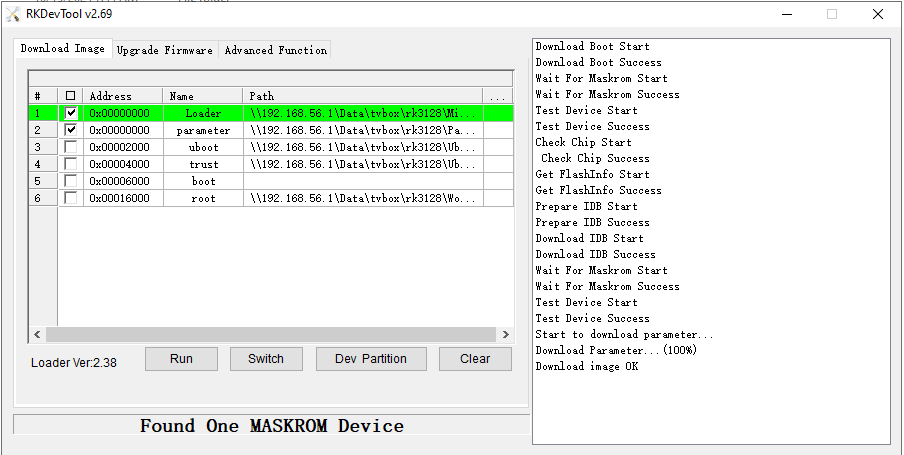
Download Image. - Add the entries shown below.
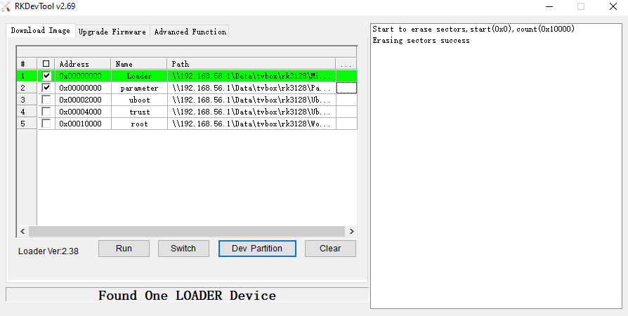
- For a full NAND/eMMC install, flash
Loader,parameter,U-Boot,Trust, androotfs.
Hybrid install: U-boot on NAND/eMMC and rootfs on USB/SD Card
This is the layout I use most often. It is flexible, lets the system run from USB or SD card, and reinstalling the OS usually means rewriting only the external rootfs.
It is also useful when the internal NAND or eMMC is only partly damaged. A common symptom is that Android starts to boot and then hangs. In that case, the internal flash may still be good enough for Loader, parameter, U-Boot, and Trust, but not reliable enough for a full root filesystem.
The board still needs working internal NAND or eMMC for these bootloader pieces:
LoaderparameterU-BootTrust
The rootfs lives on USB or SD card.
- Follow steps
1to10from the NAND/eMMC install above. - Flash only
Loader,parameter,U-Boot, andTrustto the internal NAND or eMMC. - Do not flash
rootfsto the internal storage. - Create a normal Linux partition on the USB drive or SD card.
- Write
rootfs.imgto that partition, not to the whole device.
|
|
- Boot the board. It still starts from the internal NAND or eMMC, but the system itself can run from USB or SD card.
Loader, parameter, U-Boot, and Trust still come from the internal storage. The rootfs comes from USB or SD card.
One important detail: rootfs.img is not a full disk image. It is only a filesystem image. Write it to a partition such as /dev/sdX1, not to the whole disk. Tools like BalenaEtcher are the wrong fit here because they expect an image that already contains the full partition layout.
Configuration
The rootfs starts with simple generic settings so it can boot on different board variants. After the first successful boot, connect Ethernet, ssh into the board, and run rk3128-config.
The main things worth checking are:
RAM dynamic frequency: enable it if you want better memory performance. It is off by default because some boards still hang with it enabled.Wi-Fi: choose the correct Wi-Fi chip for the board. Then reboot and usenmtuito connect.SD Card: if the board already boots from SD card, leave this alone. If you boot from another device and want the SD slot to work as storage, enable it here.Screen resolution: the default is1280x720. If your display supports it, switch to1920x1080in the display menu.
Manual configuration
The boot configuration lives in /boot/armbianEnv.txt.
This file is read by boot.cmd before the kernel starts. The format is simple:
|
|
The main parameters used by this boot script are:
verbosity: kernel log level. Default:1console: serial console device and baud rate. Default:ttyS1,115200bootlogo: enable or disable the boot splash. Default:falselogo: if set todisabled, boot.cmd switches tologo.nologorootfstype: root filesystem type. Default:ext4docker_optimizations: enable extra cgroup arguments for Docker. Default:onmtdparts: NAND/eMMC partition layout passed to the kernel. Default: it takes value from U-bootoverlay_prefix: overlay filename prefix. Default:rk3128partnum: boot partition number. Default: it takes value from U-bootfdtfile: base device tree file to load, for examplerk3128-linux.dtboverlays: space-separated list of built-in overlays to applyuser_overlays: space-separated list of custom overlays from/boot/overlay-user/rootdev: override the detected root device. Default: it takes value from U-bootrootpartname: NAND root partition name, used to build/dev/rknand_<name>. Default: it takes value from U-bootnandrootpartname: explicit NAND root partition name override. Default: it takes value from U-bootextraargs: extra kernel command-line argumentsextraboardargs: more board-specific kernel argumentsusbstoragequirks: USB storage quirks passed to the kernel
There are also a few automatic behaviors in this boot.cmd:
- If the board boots from eMMC,
emmc-enabledis forced automatically. - If the board boots from SD card,
sdcard-enabledis forced automatically andgpio2-sdcard-disabledis removed. - If the board boots from NAND,
emmc-enabledis removed automatically. - If neither
usb-otg-hostnorusb-otg-peripheralis selected,usb-otg-hostis added by default.
Built-in overlays
The files in /boot/dtb/overlay/ are named like rk3128-<name>.dtbo, but in armbianEnv.txt you only write the <name> part.
Available overlays in this build are:
ddr3-300ddr3-330ddr3-400ddr3-600ddr3-666ddr3-700ddr3-786ddr3-800dmc-disabledemmc-enabledgpio2-sdcard-disabledsdcard-enableduart1usb-otg-hostusb-otg-peripheralwlan-esp8089wlan-rtl8189eswlan-rtl8189fswlan-rtl8189ftvwlan-ssv6051
Example
This example enables UART1, forces OTG host mode, disables dynamic memory frequency scaling, and selects the RTL8189FTV Wi-Fi overlay:
|
|
If you want to boot from SD card and use ESP8089, a typical example would be:
|
|
In practice, you usually only need to change overlays, fdtfile, and sometimes extraargs or rootdev. The rest can stay at their defaults.
Conclusion
This ended up being much more than “build a kernel and boot Armbian”. The hard part was not getting one board to boot once. The hard part was turning a pile of board-specific fixes into something I could rebuild and reuse without repeating the same trial-and-error every time.
The practical result is still useful: RK3128 can run a working Armbian-based system with NAND, eMMC, SD card, Ethernet, several Wi-Fi chips, GPU acceleration, and enough configurability to deal with the usual TV-box variation. It is still based on an old vendor kernel, but at least now the setup is clean enough to document and reuse.
The obvious future work is to stop depending on the old Rockchip 4.4.194 vendor tree and move this board family to a modern Armbian stack on top of a mainline 6.x kernel. That would be a separate effort, though. The work there is less about carrying these old hacks forward and more about rebuilding the board support cleanly around proper DTS, mainline drivers, and a saner boot flow.